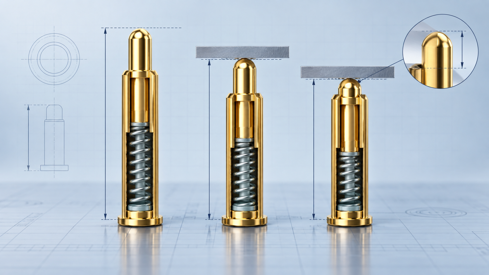
A pogo pin does not become reliable simply because its maximum travel is greater than the movement shown in a CAD model. The critical value is the pogo pin working stroke: the controlled compression range the contact actually sees after the housing, PCB, mating surface and manufacturing tolerances are assembled. That range determines whether the pin maintains force, accommodates variation, avoids bottoming out and continues to make stable electrical contact over its intended life.
This guide explains how to define working stroke on a drawing, calculate the worst-case compression window, connect stroke to force and electrical performance, and create an engineering validation plan. It is written for product, mechanical, electrical, sourcing and quality teams developing a custom spring-loaded contact or pogo pin connector—not for selecting a part from one headline number.
Working stroke is not the same as total travel
Several height and travel terms are often mixed together in requests for quotation. They should be separated before a supplier recommends a contact.
| Term | Engineering meaning | Why it matters |
|---|---|---|
| Free height | Overall pin height with no external compression. | Starting reference for calculating compression; it also has a manufacturing tolerance. |
| Total or maximum travel | Mechanical movement available before the internal structure reaches its limit. | A boundary, not the recommended operating point. Normal operation should not rely on reaching it. |
| Working height | Installed pin height at the intended mating condition. | Usually the most useful dimension for an assembly drawing. |
| Working compression | Free height minus assembled working height. | Defines how far the plunger is compressed at a particular condition. |
| Working stroke window | Minimum-to-maximum compression expected across tolerances and operating movement. | This entire window must remain inside the supplier-approved operating range. |
| Preload | Compression already present at the earliest valid contact condition. | Helps prevent intermittent contact when parts vibrate or separate slightly. |
| Reserve travel | Unused movement between worst-case operating compression and the mechanical limit. | Protects against bottoming out, shock, assembly error and tolerance drift. |
The basic relationship is simple: working compression = free height − assembled working height. The engineering work lies in defining both values at their tolerance limits and under every real operating state.
Why “use 50% of travel” is not a complete rule
Percentage-of-travel rules can be useful as an early screening shortcut, but they are not a universal specification. Two pogo pins with equal nominal travel can have different spring curves, internal clearances, plunger geometry, force limits, side-load sensitivity and recommended working ranges. A design may also need substantial preload, a large tolerance allowance or extra reserve travel for user-operated movement.
Use the contact manufacturer’s force–stroke information and approved operating window. If that information is not yet available, state the device geometry and tolerance stack rather than inventing a percentage. A supplier can then evaluate whether an existing structure fits or whether the barrel, plunger, spring and receptacle arrangement should change.
A practical method for defining pogo pin working stroke
1. Establish one dimensional reference system
Choose the PCB datum, housing datum or mating surface from which all vertical dimensions will be measured. Do not calculate the pin from one datum while the enclosure team controls the mating pad from another. Identify the pin seating surface, solder condition or receptacle position, the mating pad plane and the direction of movement. A section view is often more useful than a product photograph.
2. Define every valid assembly state
Many products have more than one relevant position: first electrical contact, nominal latch or magnetic seating, maximum user force, vibration separation and shock or drop movement. A charging dock may settle at a different height after seals compress. A hinged device may approach the pin at an angle before reaching its final position. Record the height range for each valid state and identify where continuous electrical contact is required.
3. Build the worst-case tolerance stack
Include pin free-height tolerance, PCB thickness or seating tolerance, solder stand-off, housing dimensions, mating-part dimensions, pad flatness, sealing compression and any controlled clearance. Calculate minimum compression using the shortest pin and largest assembled gap. Calculate maximum compression using the tallest pin and smallest gap. Statistical analysis can follow later; the first review should make the design boundaries visible.
4. Compare the full window with the approved contact range
The minimum-compression case must still provide enough contact force and wipe for the intended surface. The maximum-compression case must stay below the supplier’s approved working limit and leave reserve before hard stop. If either condition fails, change the working height, increase available envelope, tighten the relevant tolerance or select a different spring-loaded contact.
5. Convert individual pin force into system force
Contact force is specified at a particular compression, not as an isolated value. Multiply the force range by the number of simultaneously compressed contacts, then add seal force, magnets, latches and any misalignment moment. A 12-pin array can feel completely different from a single-pin sample. Excessive total force can lift a PCB, distort a housing or make a dock difficult to close; insufficient force can produce unstable resistance.
6. Check electrical and thermal performance at both ends
Electrical validation should cover the minimum-compression case, because that is often where force and contact stability are lowest, and the maximum-load case, where current, duty cycle and temperature rise matter most. Measure the complete current path, including mating pad, PCB trace, solder joint, connector housing and cable where applicable. A catalog current rating cannot replace assembled-device verification.
7. Evaluate lateral movement and approach angle
Pogo pins are designed primarily for axial movement. Sliding, side load or an angled mating surface can change wear, force and plunger guidance. If the product relies on magnets for self-alignment, define the residual offset after attraction and the path into final contact. The principles in our magnetic connector offset testing guide are useful when working stroke and alignment interact.
8. Freeze the values in controlled documents
Place free height, nominal working height, allowable working-height range, force requirement at defined heights and the mechanical stop on the drawing. Link the values to the approved sample and test plan. This prevents a housing change, pad change or alternate spring from silently shifting the working point during production transfer.
Worked tolerance example
Consider a hypothetical pin with a free height of 6.00 ± 0.10 mm. The assembled gap from its seating datum to the mating pad is 5.00 ± 0.15 mm.
- Nominal compression: 6.00 − 5.00 = 1.00 mm.
- Minimum compression: 5.90 − 5.15 = 0.75 mm.
- Maximum compression: 6.10 − 4.85 = 1.25 mm.
The device therefore requires a pin that performs across a 0.75–1.25 mm working-compression window—not merely at 1.00 mm. Engineering must confirm force and resistance at both limits and verify that 1.25 mm still leaves adequate reserve before the mechanical limit. These figures are an illustration, not a recommended specification for every pogo pin.
What to put in a pogo pin working-stroke specification
| Drawing or RFQ item | Information to provide | Acceptance question |
|---|---|---|
| Geometry | Available diameter, free-height envelope, seating method and mating-pad position | Does the contact fit without changing the device datum? |
| Working height | Nominal, minimum and maximum installed height | Is the entire compression window approved? |
| Force | Required force at defined heights and allowable total array force | Will the system close and remain stable? |
| Electrical duty | Voltage, continuous/peak current, duty cycle, signal or grounding task | Is temperature rise and resistance acceptable in the assembly? |
| Mating surface | Pad geometry, material, finish, flatness and contamination risk | Is contact area and wear behavior suitable? |
| Movement | Cycle count, speed, vibration, shock, lateral offset and approach angle | Does the pin remain axially guided? |
| Environment | Temperature, humidity, dust, liquids, cleaning chemicals and corrosion exposure | Are materials, plating and sealing appropriate? |
| Validation | Sample quantity, measurements, test sequence and pass/fail criteria | Can both parties reproduce the decision? |
Common failure modes caused by a poorly defined stroke
| Observed problem | Possible stroke-related cause | Engineering response |
|---|---|---|
| Intermittent contact at vibration | Minimum compression or preload is too low. | Review worst-case gap, force at minimum height and mating-pad flatness. |
| Pin sticks or does not recover | Over-compression, side load, contamination or internal damage. | Add reserve travel, mechanical guidance and contamination controls. |
| Housing is difficult to close | Total array force is higher than the mechanism can support. | Review force curve, pin count, latch/magnet force and structural deflection. |
| Resistance changes after cycling | Working point, wiping path, plating or pad condition is unsuitable. | Measure at controlled heights before and after the agreed cycle test. |
| PCB or solder joint damage | Bottoming, excessive axial load or impact is transferred to the board. | Introduce a housing stop and verify mounting strength separately. |
Validation plan: test the window, not only the nominal point
A useful sample plan measures free height, force and resistance before cycling; tests minimum, nominal and maximum working compression; applies the actual current profile; and repeats measurements after the agreed mechanical and environmental sequence. Use the real mating pad or a documented equivalent. Record sample revision, pin lot, fixture, test current, measurement location, temperature and dwell time.
For a new custom project, start with the inputs in our engineering sampling checklist. If the contact is part of a magnetic interface, also evaluate supplier control of the pin, magnets, housing and assembly using our custom magnetic connector factory checklist.
Related product families
- Custom pogo pins for individual spring-loaded power, signal, grounding and test contacts.
- Pogo pin connectors when pitch, housing, alignment and total mating force must be evaluated together.
- Magnetic connectors when working stroke interacts with attraction, offset and device-side guidance.
Frequently asked questions
What is a good working stroke for a pogo pin?
There is no universal value. A good working stroke is the range that preserves adequate force and electrical stability across the device tolerance stack while remaining inside the approved contact window with reserve before the mechanical limit.
Should a pogo pin operate at half of its total travel?
Half travel may be an early reference for some structures, but it is not a substitute for the supplier’s force–stroke curve, allowable range and the device’s worst-case dimensions.
Is working stroke the same as working height?
No. Working height is the installed physical height. Working compression is the change from free height to that installed height. A working-stroke window covers all expected compression states.
How much reserve travel is required?
It depends on tolerance, shock, assembly control and the contact design. Define the maximum operating compression first, then confirm a reserve with the manufacturer rather than adopting an arbitrary universal margin.
Does higher compression always reduce contact resistance?
No. Adequate force supports stable contact, but resistance also depends on plating, surfaces, geometry, contamination, current and measurement method. Excess compression can damage the contact or assembly.
Where should the mechanical hard stop be placed?
The housing or mechanism should normally limit movement before damaging load is transferred through the pogo pin. Its position should account for all relevant tolerances and dynamic movement.
Can the same stroke specification be used for every pin in an array?
Only if coplanarity, housing stiffness and mating-pad flatness support it. Multi-pin connectors require review of load sharing, local deflection, pitch, alignment and total force.
What should I send for a custom pogo pin review?
Send a section drawing with datums and tolerances, the mating-part geometry, pin assignment, voltage/current profile, required force or total mating force, environment, cycle target, verification criteria and expected quantity.
Define the contact around the assembled device
Yongtan develops pogo pins and spring-loaded connector assemblies around confirmed device requirements. Share your drawing, nominal and worst-case working heights, electrical load, mating surface, environment and expected volume with Bella. We can review whether a reference structure is suitable, identify missing inputs and define the sample and verification boundary before tooling or production release.