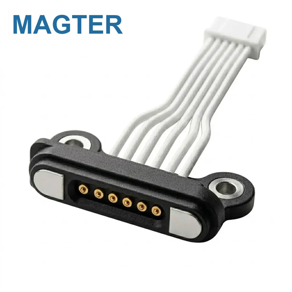
A useful magnetic data cable sample begins with enough information to build and evaluate the correct interface. Missing items can be resolved during review, but assumptions should be visible and controlled.
1. Application and user action
Describe the device, what the cable must do, how users approach and remove it, the expected mating frequency and any special safety or service condition.
2. Device and interface drawings
Provide 2D or 3D data for the available space, PCB or FPC location, enclosure opening, mating direction, mechanical stops and tolerances when available.
3. Pin map and electrical conditions
Define each contact, polarity, ground, voltage, current and allowable resistance or temperature-rise condition. Include protection or sequencing requirements that affect the interface.
4. Communication task
Name the required protocol or signal type, host and device configuration, data rate if relevant, shielding or grounding needs and the functional test used to confirm operation.
5. Cable and input end
Confirm the input connector, cable length, conductor or shielding direction, outer material, flexibility, color, strain relief and any labeling or packaging requirement.
6. Environment and reliability
State exposure to moisture, temperature, salt, chemicals, vibration, pull, flex or repeated mating. Define test methods and acceptance limits for the conditions that matter to the device.
7. Sample stage and records
Specify sample quantity, target timing, whether the design is concept or production intent, and which drawings, reports or inspection records are expected.
8. Forecast and production context
Share expected annual volume, ramp timing and assembly location when known. These inputs influence tooling, process planning, inspection and the most practical development route.
Website guidance supports early selection and communication. Final dimensions, materials, electrical performance and validation requirements follow the project-approved drawings, specifications and test records.