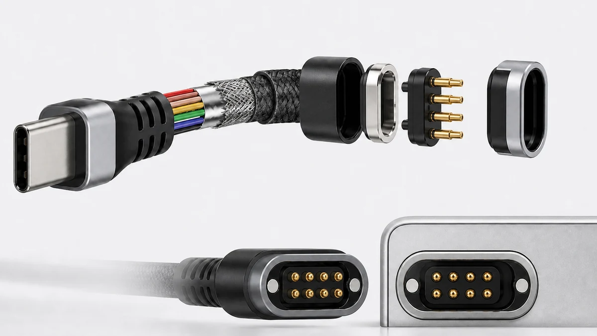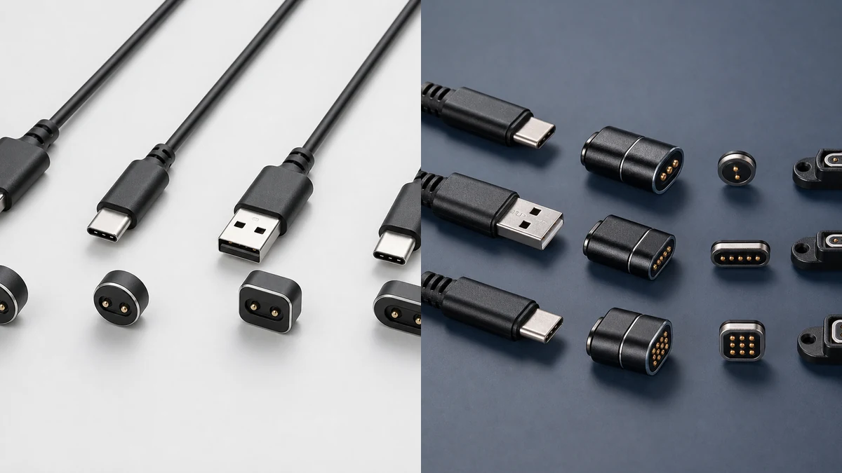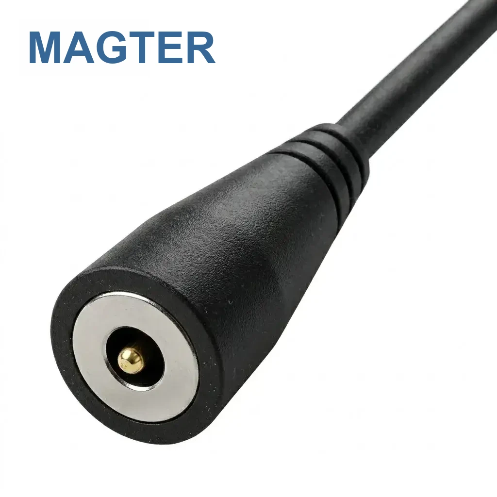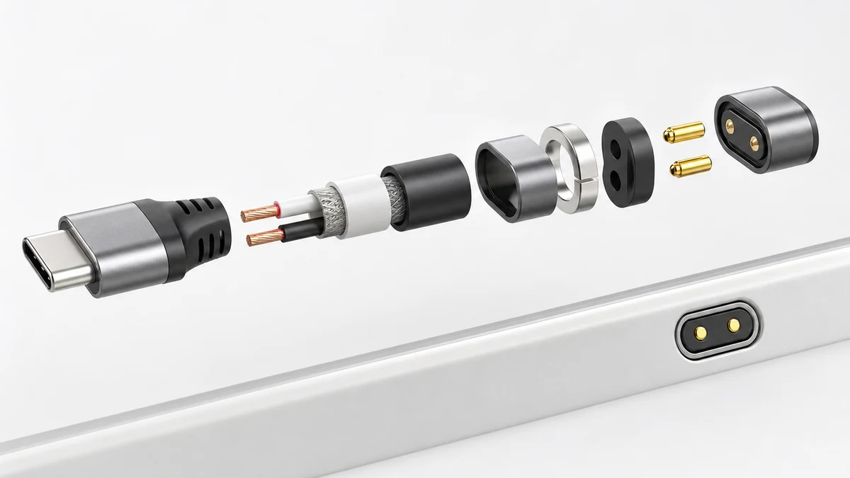
A magnetic charging cable combines an input, cable, magnetic head and device mating structure. Pogo pins provide compliant electrical contact; magnets assist attachment but do not replace mechanical guidance.
The main components and their roles
| Component | Role | Design considerations |
|---|---|---|
| Input connector | Connects to the power source or host. | Interface type, supply conditions, protocol and termination. |
| Cable | Carries power and any specified signals. | Conductors, gauge, length, jacket, flexibility and shielding. |
| Pogo pin contacts | Establish electrical contact at the defined compression. | Travel, working compression, stability and contact-surface condition. |
| Magnets and magnetic circuit | Assist attachment and retention. | Polarity, attraction direction and nearby components. |
| Insulators and housing | Separate contacts and form the interface. | Strength, temperature, assembly, appearance and polarization. |
| Device receptacle | Mates with the cable head and connects to the PCB. | Location, stops, seals, soldering and installation tolerances. |
What the pogo pin contributes
The spring structure accommodates a defined amount of contact and assembly variation. Selection considers current, working travel, space, expected cycles and environment. Yongtan provides standalone pogo pins as a core product family, as well as integrating them into connectors and magnetic assemblies.
Why magnets cannot replace mechanical location
Attraction alone does not control lateral movement, rotation, reverse connection or working compression. Guides, stops, anti-reversal features and mating profiles keep contacts in the intended position and help achieve predictable release under load.
Sealing must follow the system boundary
Ingress performance may depend on the cable overmold, head insulation, receptacle, sealing rings, enclosure mounting and final assembly. A change at any interface can change the result. Test the identified model and installation state under approved conditions.
Frequently asked questions
Are more pogo pins always better?
No. The count follows power, ground, detection, identification and signal functions, as well as spacing, available space, assembly and cost.
Can magnets alone locate the connector?
Stable integration normally also requires guidance, stops, polarization and controlled contact compression.
Can a structure drawing be reused unchanged in another device?
Not automatically. Device space, receptacle, enclosure and circuit requirements must be reviewed for the new assembly.