Simultaneous charging and data require a defined pin map, suitable conductors and termination, stable contacts and full-device protocol verification. More pins alone do not establish data capability.
Review the complete power-and-data path
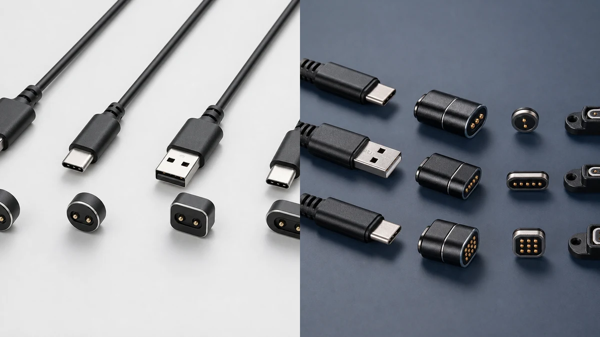
- The input connector receives the specified power and communication channels.
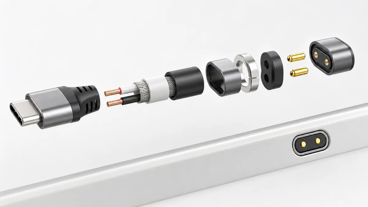
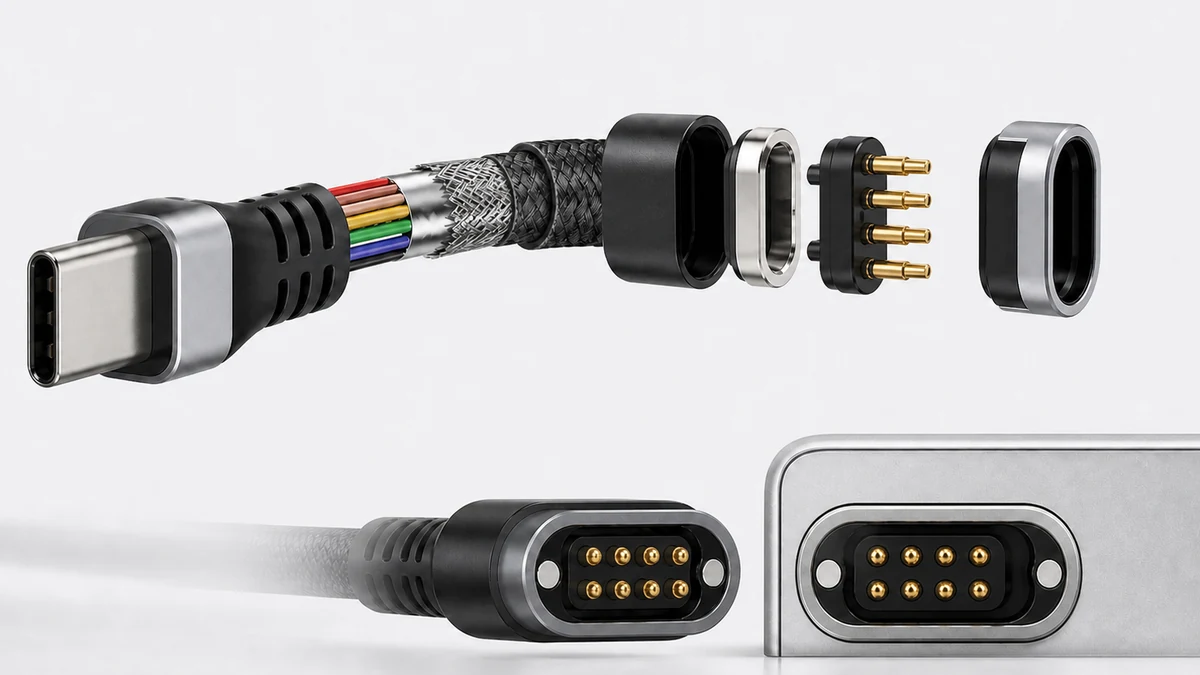
- Cable conductors and shielding implement the assigned power, ground and signal circuits.
- Head terminations map these circuits to the magnetic interface pins.
- The device receptacle connects each pin to the correct PCB circuit.
- The assembled system is checked with the intended protocol, length, load and environment.
Approve one unambiguous pin assignment
Number the cable-side and device-side pins using the same stated viewing direction. Identify power, ground, detection, identification and single-ended or differential signals as applicable. Confirm polarity, reverse-mating prevention and permitted orientation. Drawings, schematics, wiring tables and test fixtures must describe the same mapping.
Cable construction affects communication
Power circuits depend on conductor cross-section, voltage drop and heating. Data circuits may also depend on conductor arrangement, twist, impedance, shielding, crosstalk and grounding. Protocol, rate and cable length set the design boundary; results for one sample cannot be applied to every model.
Verification by development stage
| Stage | Checks to agree |
|---|---|
| Before sampling | Pin assignment, interfaces, length, protocol, supply and device geometry. |
| Sample evaluation | Continuity, polarity, stable contact, communication and assembled fit. |
| Reliability evaluation | Applicable bending, pull, environmental and repeated-mating checks, followed by functional retesting. |
| Production | Wiring, continuity, critical electrical items, appearance and batch traceability. |
Define the OEM / ODM scope
Yongtan can review the magnetic head, pin assignment, input, cable, device receptacle, samples and production scope. Provide the target protocol or signal requirements and agree the test conditions and pass criteria with the engineering team.
Frequently asked questions
Does a four-pin magnetic cable necessarily carry USB data?
No. Data capability depends on pin functions, cable construction, termination, contact interface, device circuits and full protocol verification.
Can the data cable also provide charging?
This can be evaluated when both power and data paths meet their requirements under the target load and assembled-device conditions.
Does acceptable contact resistance prove stable data?
No. Contact resistance is one electrical measure; the complete channel, shielding, signal quality and protocol performance must also be assessed.