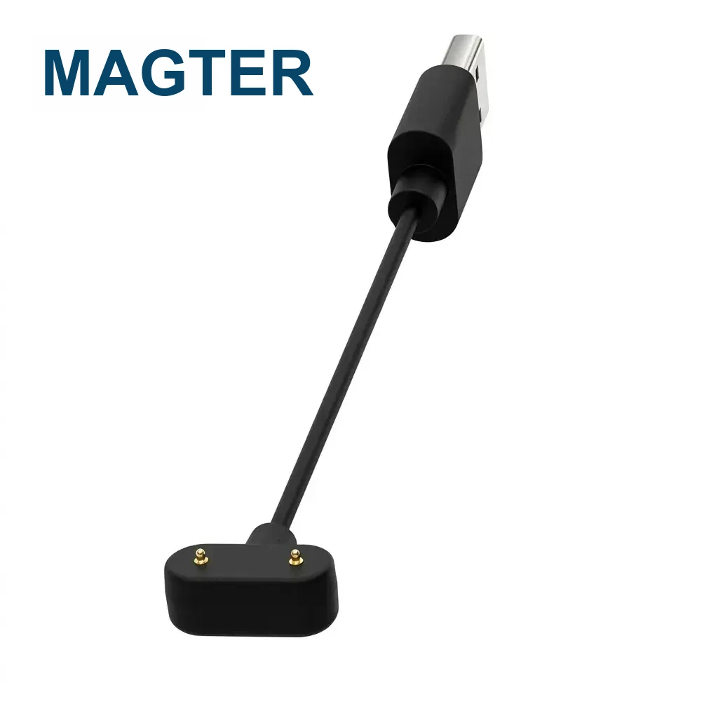
A connector snapping into place is a useful visual demonstration, but it is not a complete offset test. Engineering evaluation needs a defined starting displacement, final contact position and electrical result under repeatable device conditions.
What offset testing should answer
The test should show how much initial lateral or angular displacement the interface can recover from, whether it reaches the intended mechanical stop and whether every required circuit remains stable. The starting direction matters because magnetic attraction and enclosure guidance may not be symmetrical.
Record the mechanical conditions
Document the connector model and revision, enclosure geometry, cable exit direction, starting offset, approach speed, fixture, magnetic polarity and any rotational freedom. A result without these conditions is difficult to reproduce or compare.
Measure the electrical result
Check continuity during approach and after seating. Where relevant, monitor contact resistance, voltage drop, temperature rise and signal behavior. A visually centered connector can still have an unstable contact if spring travel, contamination or tolerance stack-up is unfavorable.
Repeat across samples and orientations
Evaluate more than one mating pair and repeat the movement from the expected user directions. Include the assembled device and production-intent cable because fixture-only tests may omit housing friction, cable torque and real mechanical stops.
Define acceptance before testing
Agree the permitted offset, number of cycles, electrical limits and failure definition in advance. Store videos as supporting evidence, but use controlled measurements and the approved test record for the release decision.
Website guidance supports early selection and communication. Final dimensions, materials, electrical performance and validation requirements follow the project-approved drawings, specifications and test records.