Structure and mounting
DIP, SMT, double-ended, solder-cup, right-angle and threaded structures are evaluated around the real PCB and enclosure.
Custom spring-loaded contacts for charging, signal, grounding, testing and compact device integration.
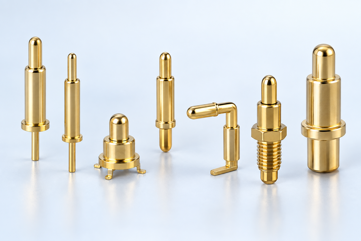
The filter structure follows the same five-family classification used on the Chinese catalog. A matching case is a development reference, not a guaranteed drop-in design.
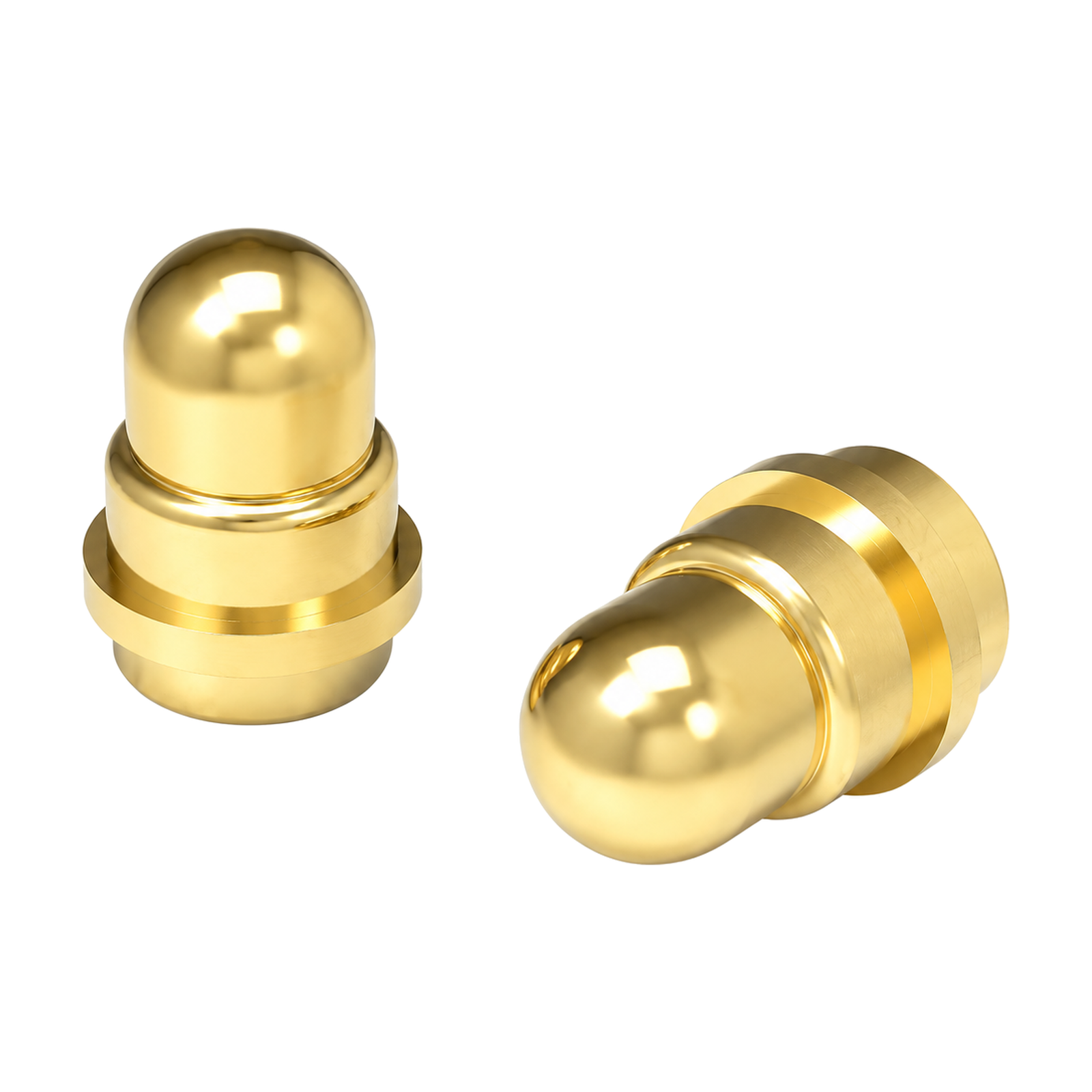 CUSTOM PROJECT REFERENCECustom DIP Through-Hole Pogo Pin, 1A Max / DC 12V – YT-PP-566SKU YT-PP-566Rated Current1A MaxRated VoltageDC 12V
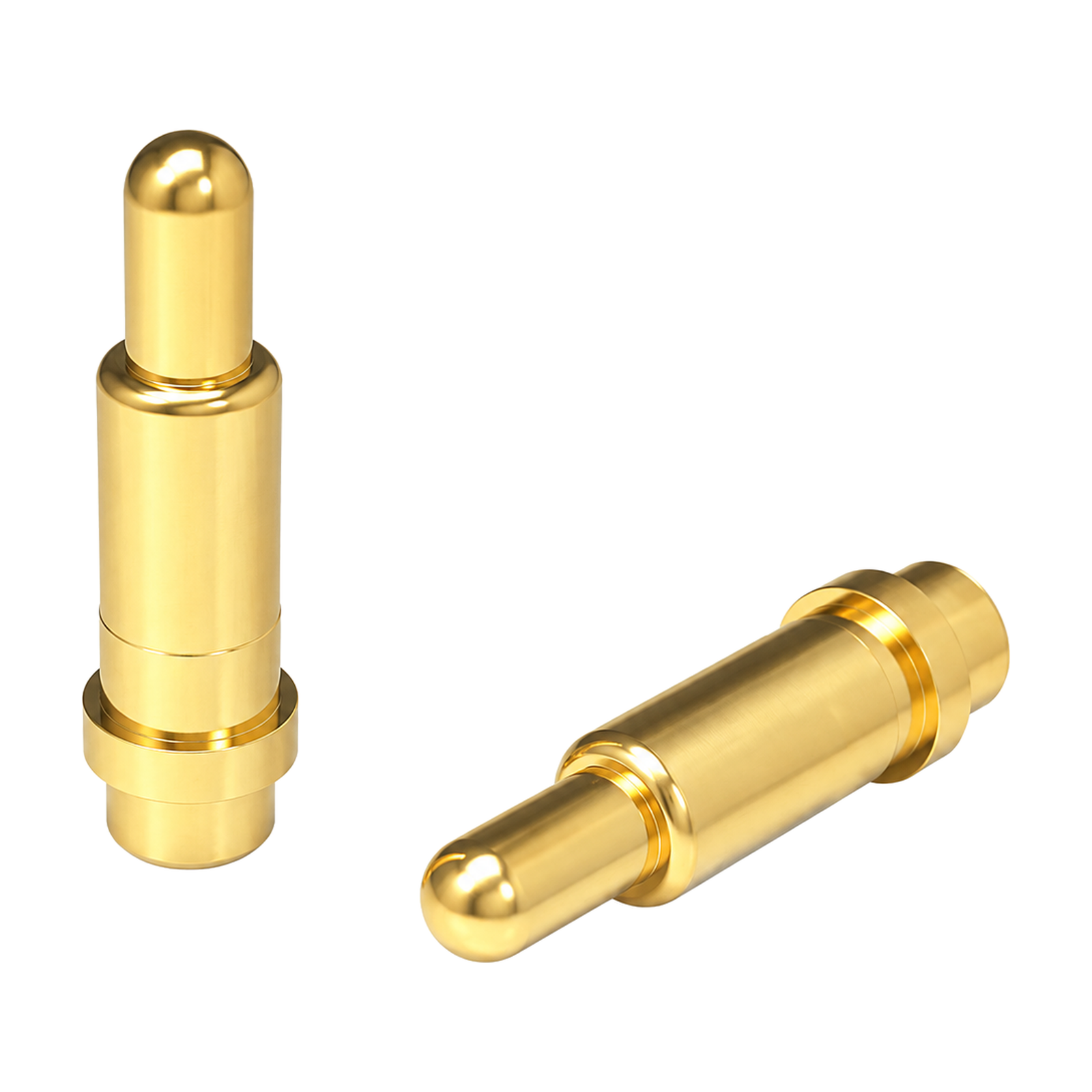 CUSTOM PROJECT REFERENCECustom DIP Through-Hole Pogo Pin, 1A Max / DC 12V – YT-PP-565SKU YT-PP-565Rated Current1A MaxRated VoltageDC 12V
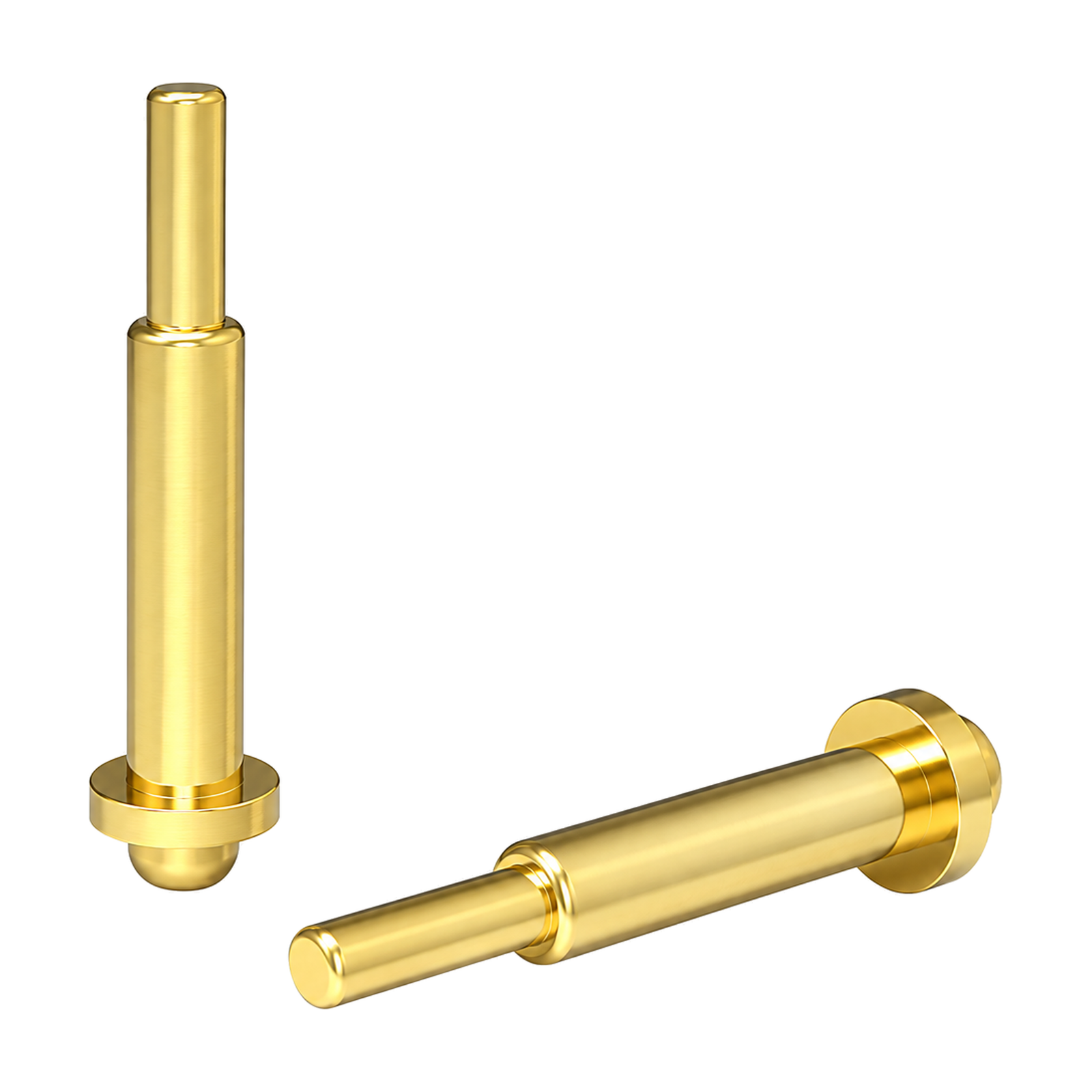 CUSTOM PROJECT REFERENCECustom DIP Through-Hole Pogo Pin, 2A Max / DC 12V – YT-PP-564SKU YT-PP-564Rated Current2A MaxRated VoltageDC 12V
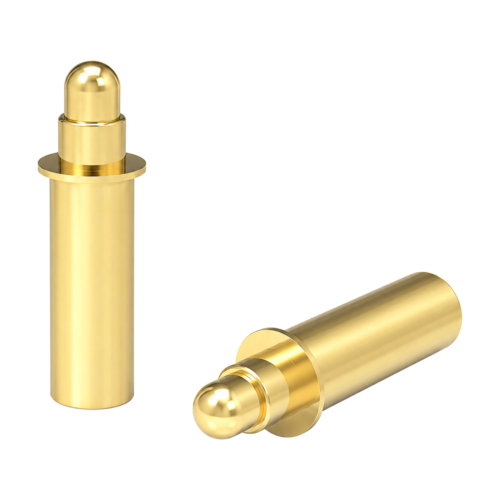 CUSTOM PROJECT REFERENCECustom DIP Through-Hole Pogo Pin, 8 A / DC 12V – YT-PP-563SKU YT-PP-563Rated Current8 ARated VoltageDC 12V
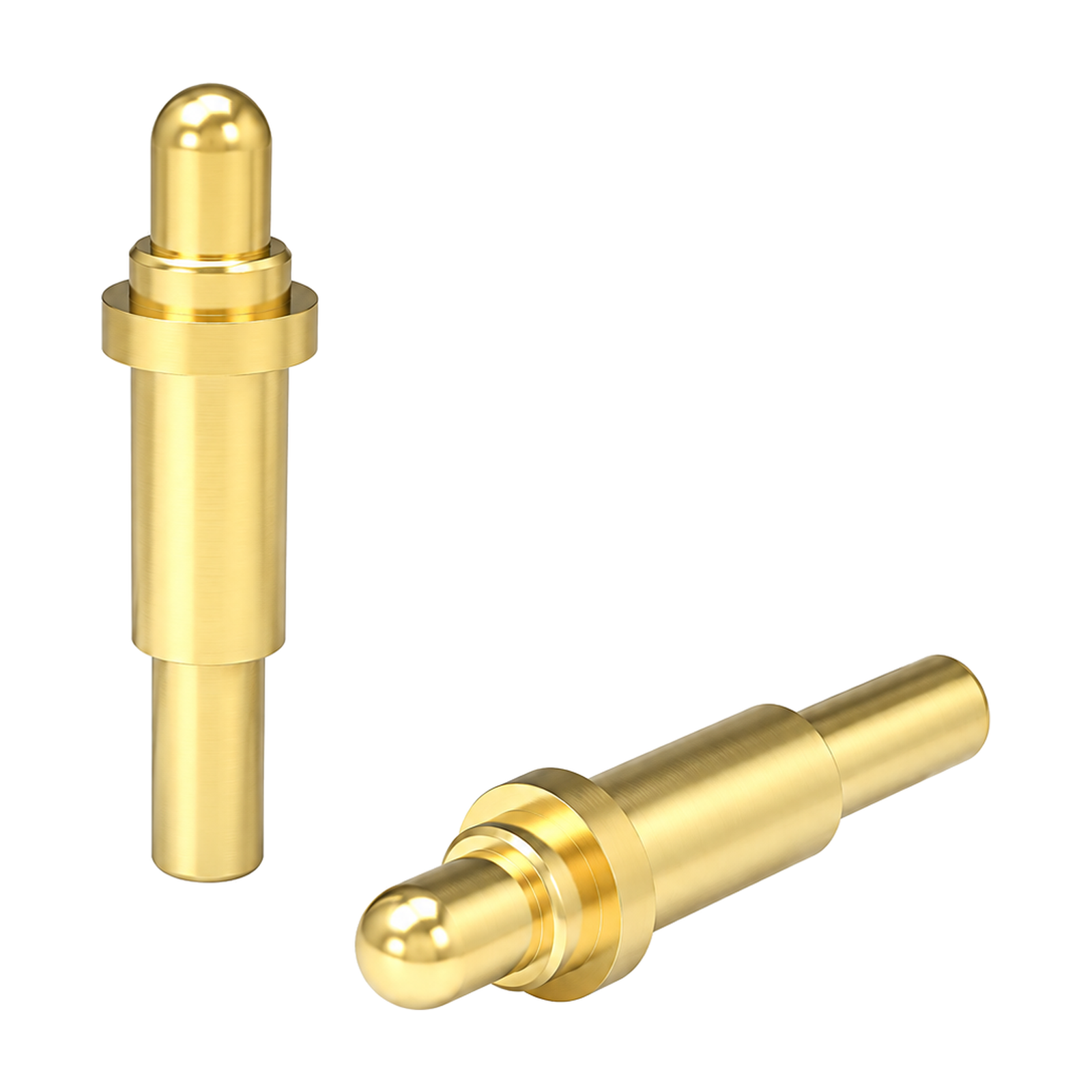 CUSTOM PROJECT REFERENCECustom DIP Through-Hole Pogo Pin, 1 A / DC 12V – YT-PP-562SKU YT-PP-562Rated Current1 ARated VoltageDC 12V
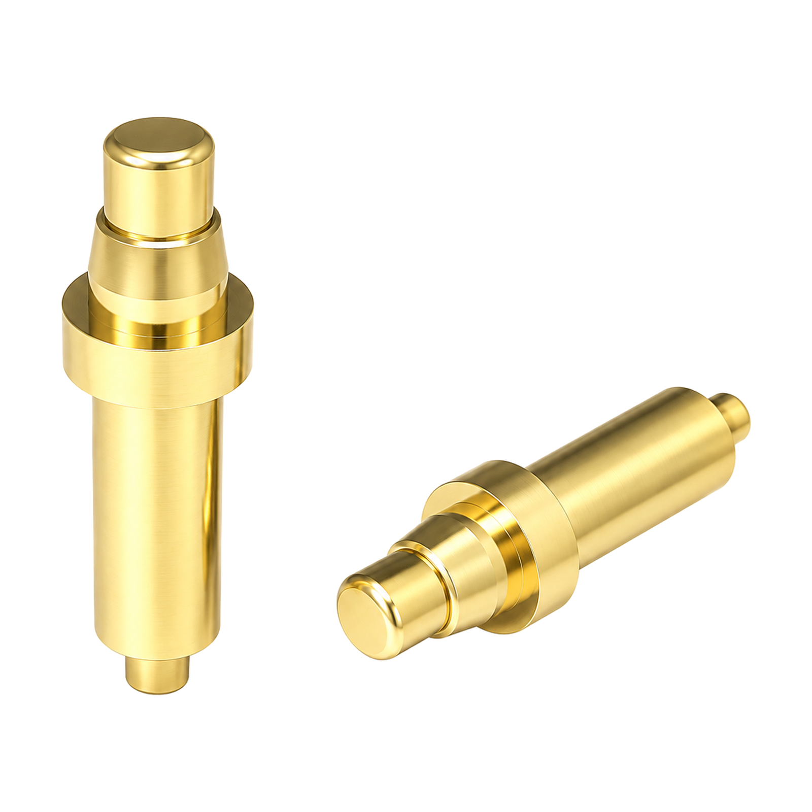 CUSTOM PROJECT REFERENCECustom DIP Through-Hole Pogo Pin, 15 A / DC 12V – YT-PP-561SKU YT-PP-561Rated Current15 ARated VoltageDC 12V
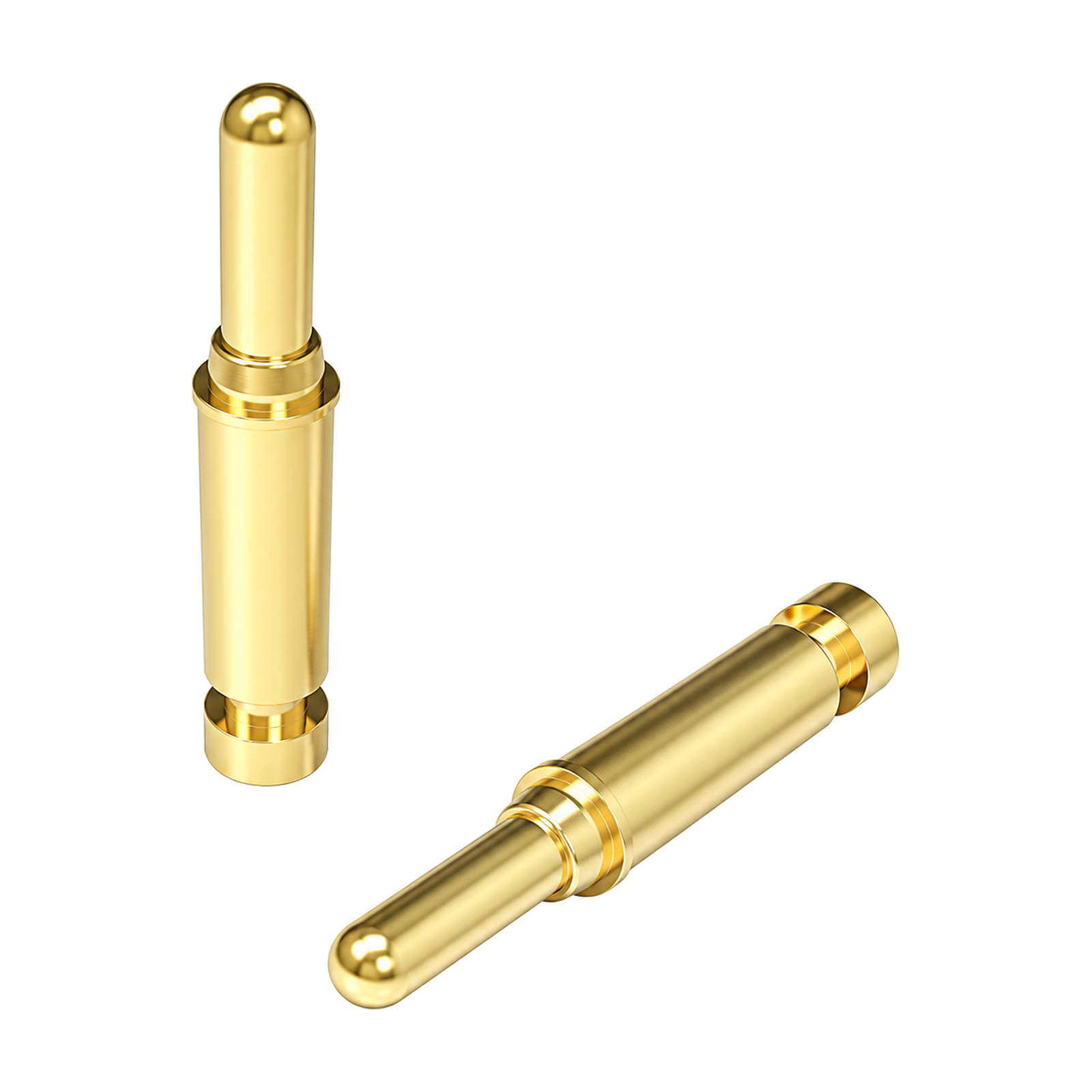 CUSTOM PROJECT REFERENCECustom High-Current Pogo Pin, 5 A / DC24V – YT-PP-560SKU YT-PP-560Rated Current5 ARated VoltageDC24V
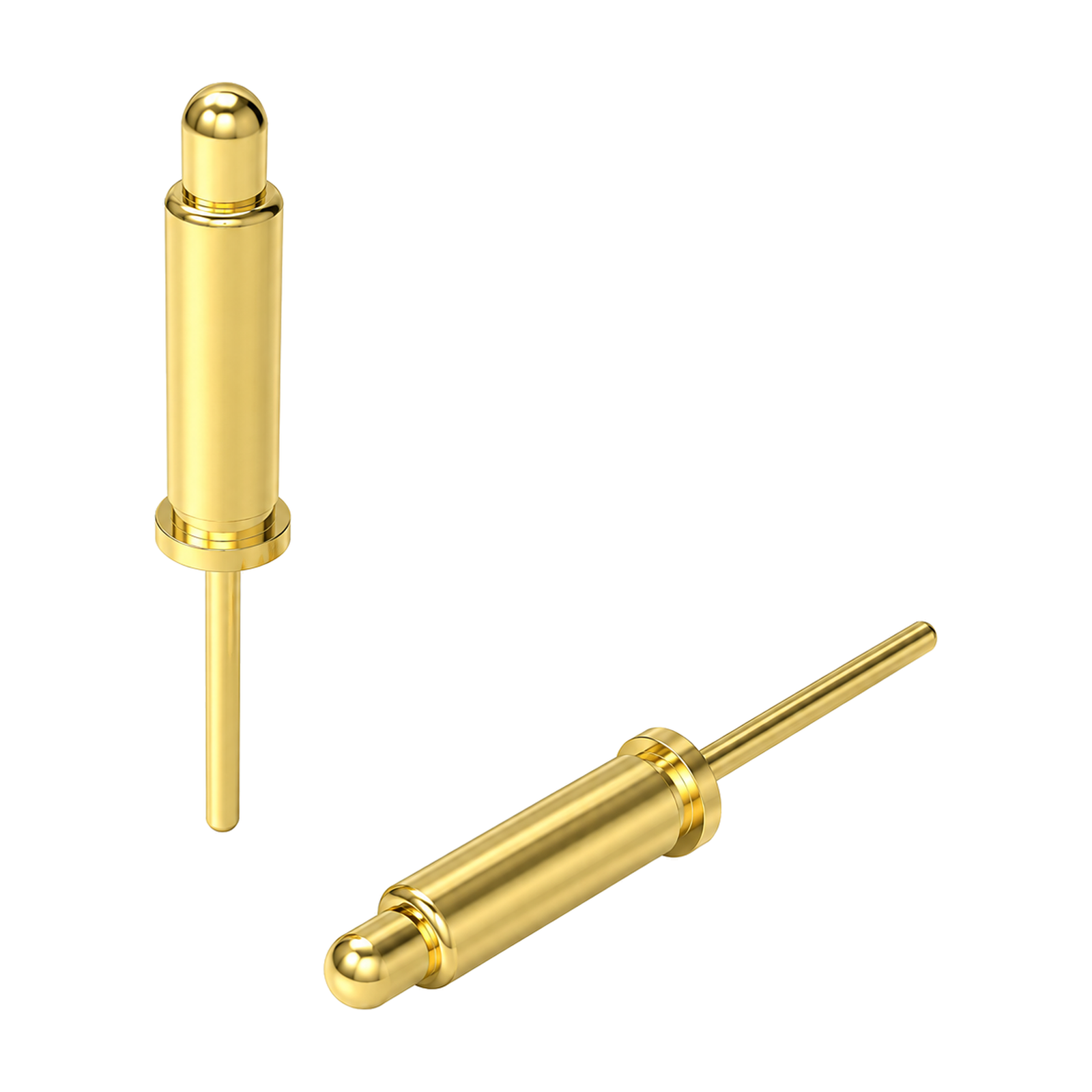 CUSTOM PROJECT REFERENCECustom High-Current Pogo Pin, 5A Max / DC12V – YT-PP-559SKU YT-PP-559Rated Current5A MaxRated VoltageDC12V
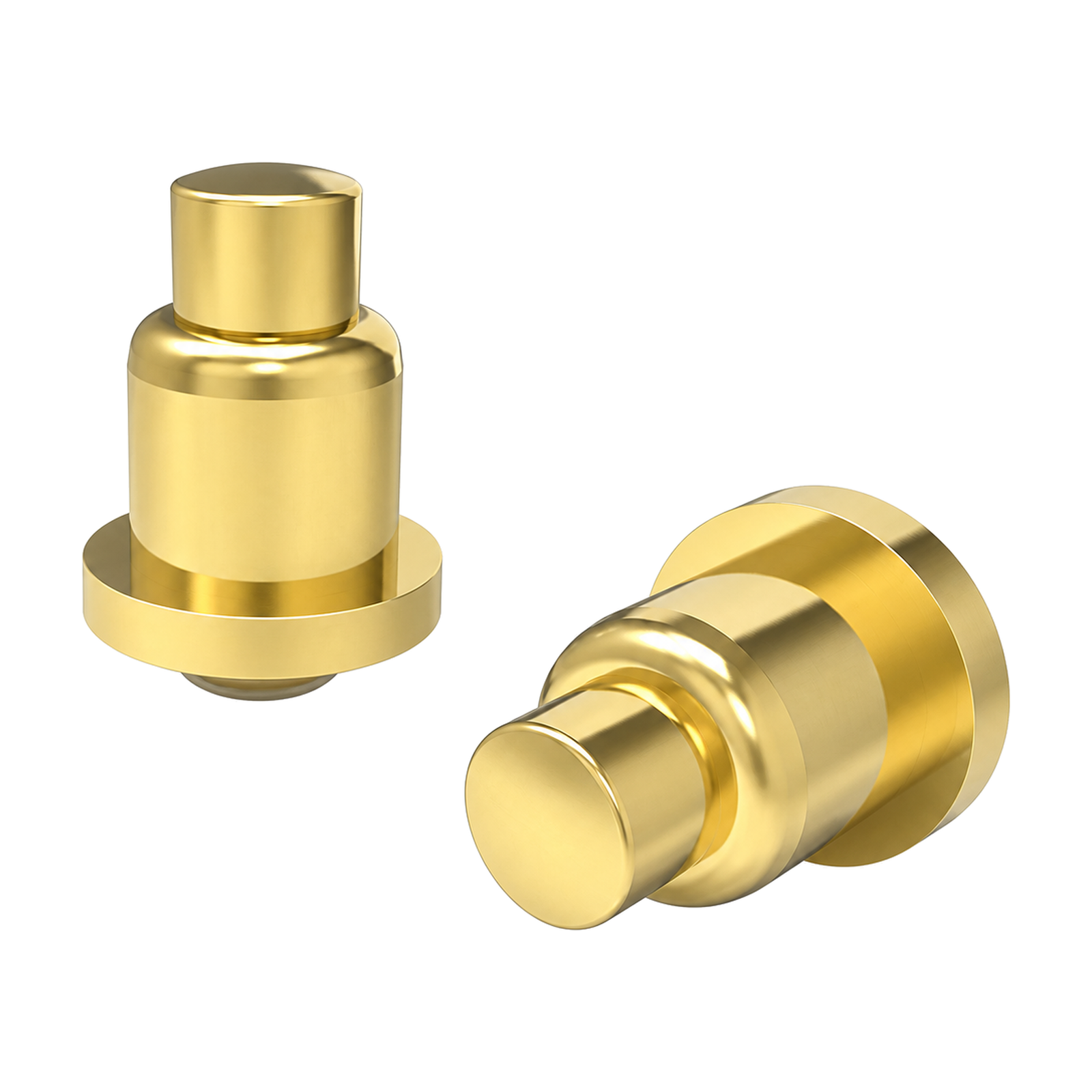 CUSTOM PROJECT REFERENCECustom Solder-Cup Pogo Pin – YT-PP-558SKU YT-PP-558
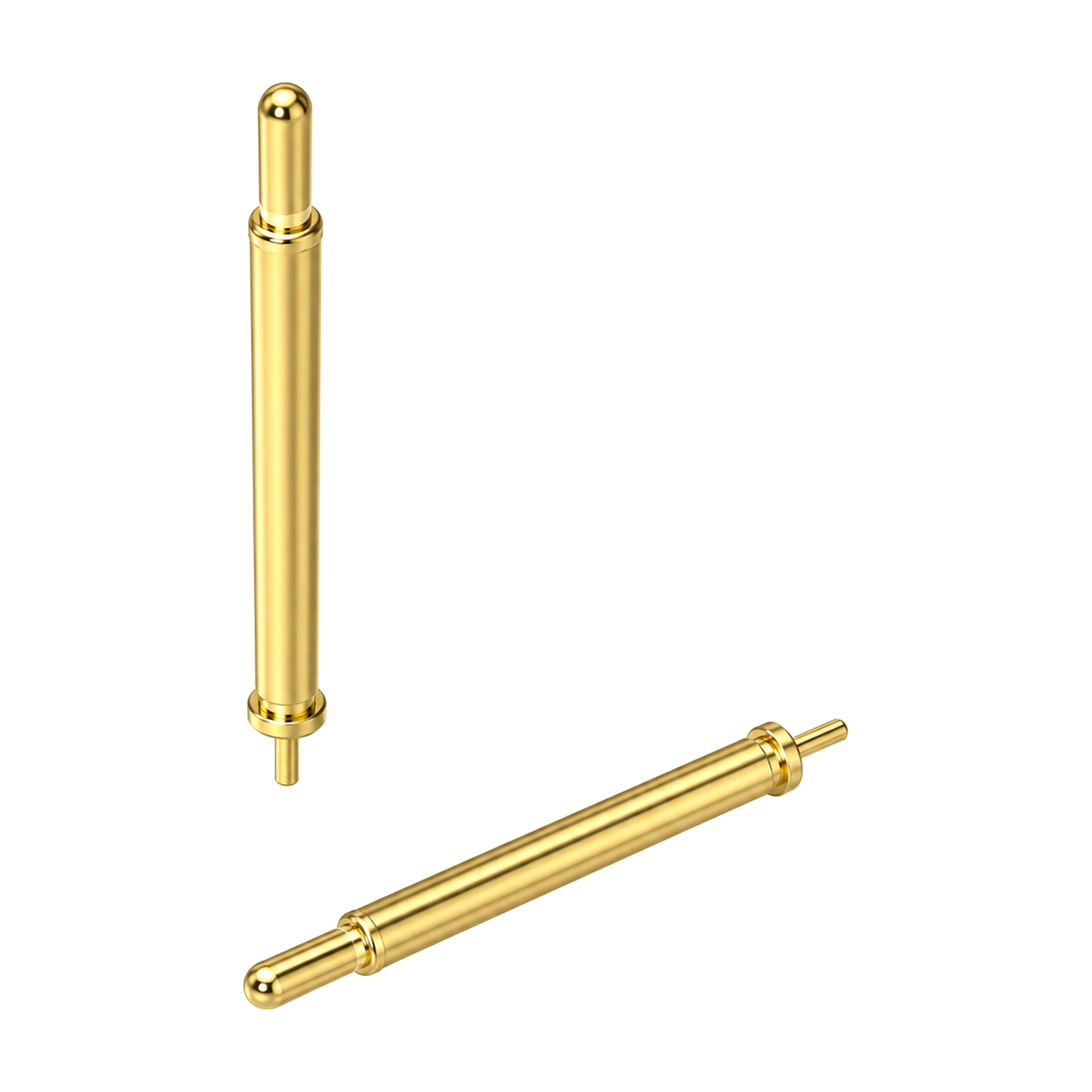 CUSTOM PROJECT REFERENCECustom DIP Through-Hole Pogo Pin – YT-PP-557SKU YT-PP-557
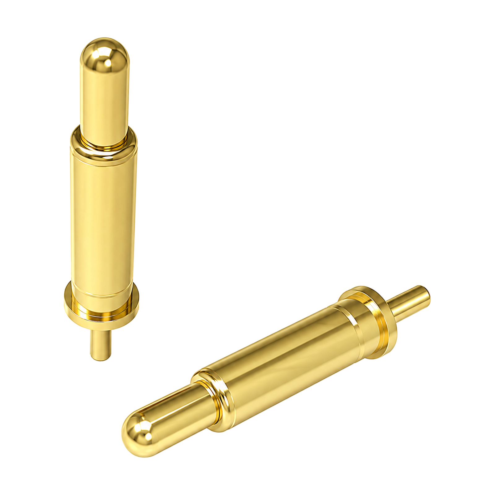 CUSTOM PROJECT REFERENCECustom DIP Through-Hole Pogo Pin – YT-PP-556SKU YT-PP-556
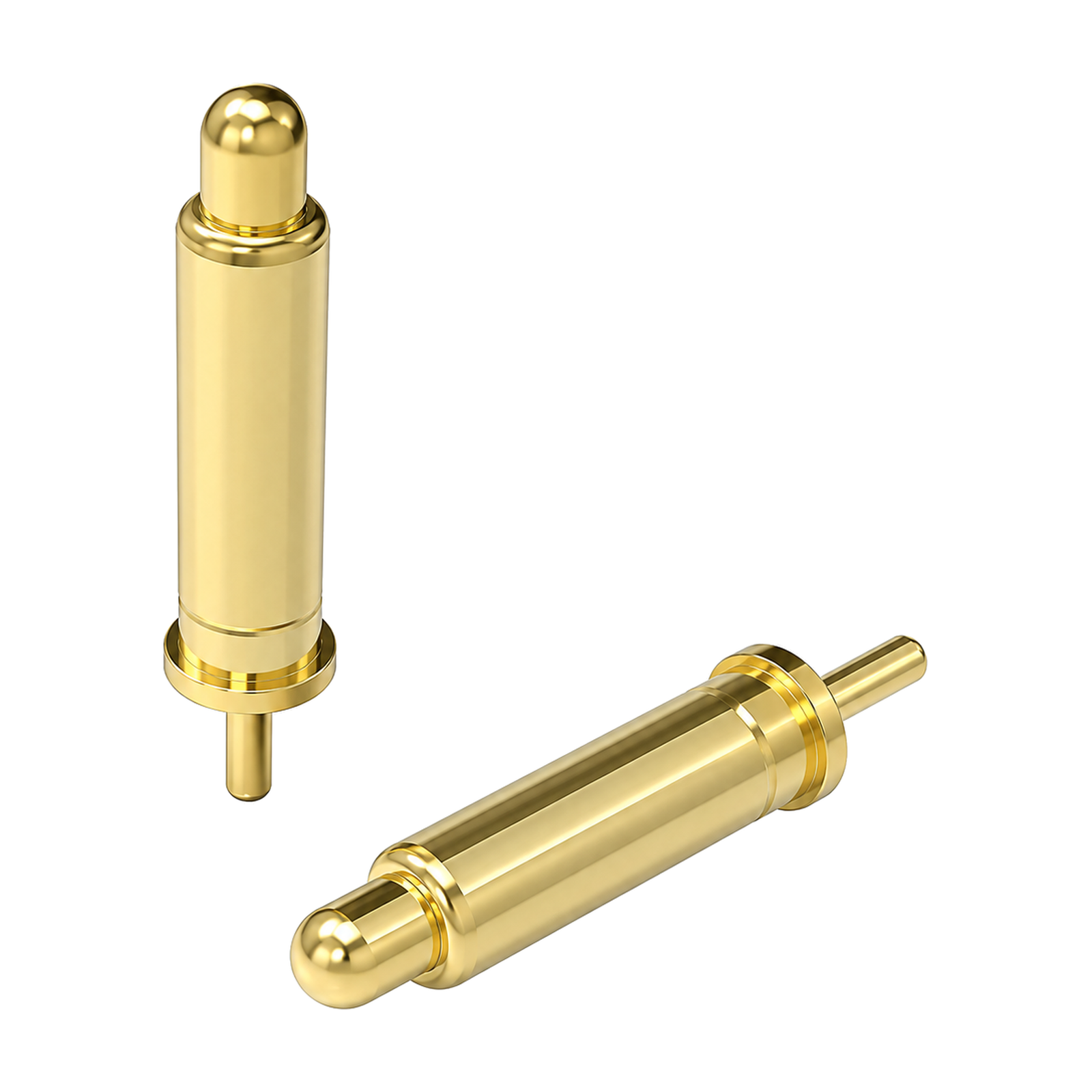 CUSTOM PROJECT REFERENCECustom DIP Through-Hole Pogo Pin – YT-PP-555SKU YT-PP-555
DIP, SMT, double-ended, solder-cup, right-angle and threaded structures are evaluated around the real PCB and enclosure.
Current, voltage, contact resistance, force, travel, materials and plating are confirmed for each project.
The final design is verified in the actual assembly and operating environment.
Select the contact structure first, then define how it operates in your assembled device. A catalog current value alone does not define a suitable contact.
Provide the compressed height and tolerance stack at the mating position; do not equate full travel with the intended working stroke.
Define the required contact force at working height and the geometry, material and finish of the mating pad.
State the load profile, duty cycle and allowable temperature rise for the final assembly, alongside voltage and current requirements.
Concise answers for product teams evaluating a custom precision-contact or magnetic-connection project.
Custom spring-loaded contacts for charging, signal, grounding, testing and compact device integration. The final design is released only after the project requirements are confirmed.
Start with structure type, installation space, electrical assignment, operating environment and expected service life. Use the filters as a reference, then confirm the full requirement with engineering.
Yes. The listed products are customer case references. Dimensions, materials, plating, cable, pin assignment and verification requirements can be reviewed for a new project.
Share your drawings, application and target requirements with Bella for an engineering review.