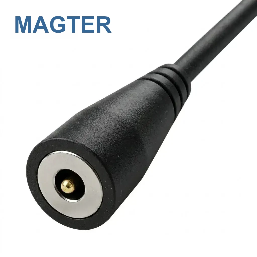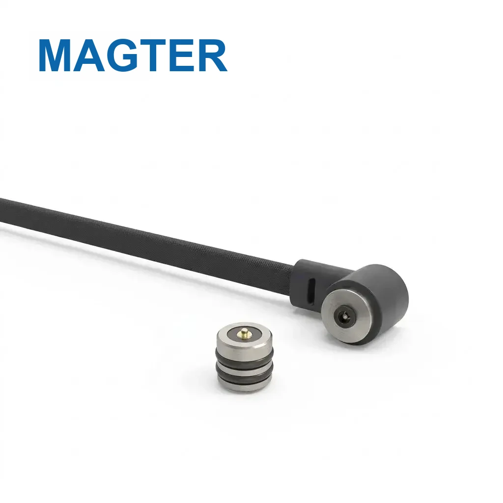
Magnetic connector, magnetic charging cable and magnetic data cable describe different project boundaries. Choosing the right family first makes the drawings, quotation and validation scope much clearer.
Magnetic connector
This normally refers to the device-side or module-side magnetic interface, such as a PCB, FPC or enclosure-mounted assembly. Selection focuses on geometry, mounting, pin count, magnetic force, alignment, spring travel and the electrical assignment.
Magnetic charging cable
This is a complete cable assembly intended primarily to deliver power. Its scope includes the magnetic head, conductor size, cable length, input connector, strain relief, polarity and charging conditions. Charging-only should not be described as data capable.
Magnetic data cable
This assembly combines power with defined data or signal paths. In addition to charging requirements, it needs a confirmed protocol, signal pin map, cable construction, shielding or grounding strategy and system-level functional validation.
How to choose
Start with the deliverable: device interface only, full power cable, or full power-and-data cable. Then define the device space, pin assignment, electrical conditions, input end, cable construction, user action, environment and verification plan.
Why the distinction matters
Using the correct family prevents missing scope in quotations and samples. It also helps search and engineering teams understand whether a page describes a component, a cable assembly or a complete communication path.
Website guidance supports early selection and communication. Final dimensions, materials, electrical performance and validation requirements follow the project-approved drawings, specifications and test records.