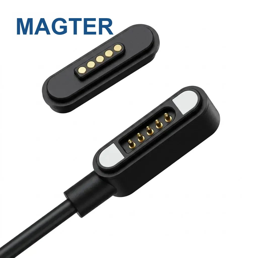
Successful charging proves that part of the power path is working. It does not confirm the host, protocol, signal conductors, magnetic pin map or device-side data routing.
Chain 1: host and protocol
Test with a known compatible host, port, power state and software configuration. Confirm that the selected input connector and cable are intended to carry data; some power sources and charging-only cables do not expose the required communication path.
Chain 2: cable conductors and shielding
Check continuity end to end for every signal, ground and power conductor. Review cable construction, conductor assignment, shielding, drain connection and solder joints against the approved drawing. Flexing near the cable head can reveal an intermittent joint.
Chain 3: magnetic interface
Verify the mating orientation, pin map, polarity, pogo-pin travel, contact cleanliness and alignment. Confirm that the device and cable revisions use the same contact definition. A reversed or shifted signal assignment may still leave the power contacts working.
Chain 4: device routing and firmware
Inspect the device receptacle, PCB or FPC routing, protection components and firmware state. Compare the magnetic interface with a direct wired reference where possible to isolate the cable from the device.
Record the failing condition
Capture the exact cable, device, host, orientation and software state. Change one variable at a time and record the result. This produces actionable evidence for engineering instead of a general statement that the cable does not work.
Website guidance supports early selection and communication. Final dimensions, materials, electrical performance and validation requirements follow the project-approved drawings, specifications and test records.